CONTENT
1. CONVERGE Pro 2 USB Expander
2. Unpacking
A. Parts Included
B. Parts Not Included
C. Tools Required
3. Quick-Start Overview
4. Mount The USB Expander
A. Rack Shelf Mounting
B. Mounting Under The Table
C. Mounting On The Wall
D. Mounting Above The Ceiling
5. Connections
A. Back Panel
B. Front Panel
6. Configure The USB Expander
7. Part Numbers
CONVERGE PRO 2 USB EXPANDER
Congratulations on purchasing your USB Expander.
The CP2 USB expander is a flexible, easy-to-use USB audio interface for CP2 units that gives you an additional audio USB port with 2 x 2 audio channels in compact form. It is designed specifically for CP2 DSP Mixers.
IMPORTANT: The CP2 USB expander can only be used only with CONVERGE Pro 2 systems. It is not compatible with first generation CONVERGE Pro.
UNPACKING
Parts Included
The following items are included with the CP2 USB Expander:
- CP2 USB Expander Unit
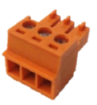
- 1 Qty 3.81mm Terminal Block Connector, 3 Position (Orange) for RS-232 connection.
- 1 USB Cable, Type A to Type B, 6 Ft (1.8M) for USB (Audio) connection.

Verify that all items have been received. If there is any issue, please contact your ClearOne representative.
Parts Not Included
Note: Installer is responsible for ensuring CP2 expander is firmly attached to sturdy support that holds weight of expander unit and mounting hardware.
The following parts are not included with the CP2 USB Expander:

Tools Required
The following tools are required to install the USB expander:

QUICK-START OVERVIEW
Perform these steps in the following order to use the USB Expander in your CP2 system:
1. Mount the USB Expander. (Optional)
2. Connect the USB Expander.
3. Configure the USB Expander.
MOUNT THE USB EXPANDER
The USB expander can be mounted in 1) a rack shelf, 2) under the table, 3) on the wall, 4) above the ceiling. Each mounting type is explained below. Mounting hardware is not provided.
Rack Shelf Mounting
ClearOne offers a standard 1U rack shelf with 20lb (9kg) weight capacity.
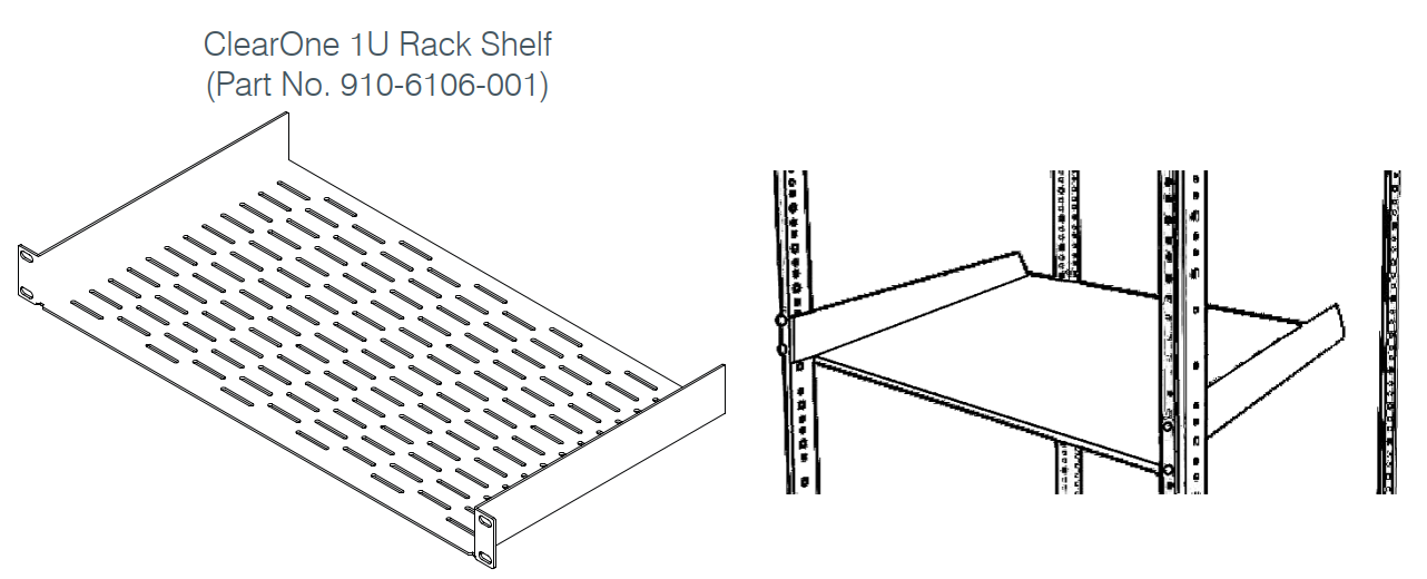
1. Determine location for rack shelf.
2. Align mounting holes on rack shelf mounting ears with holes on the rack (at determined location).
3. Insert the four #10-32 screws included with the ClearOne 1U rack shelf (or proper screws for your 3rd-party mount) and tighten.
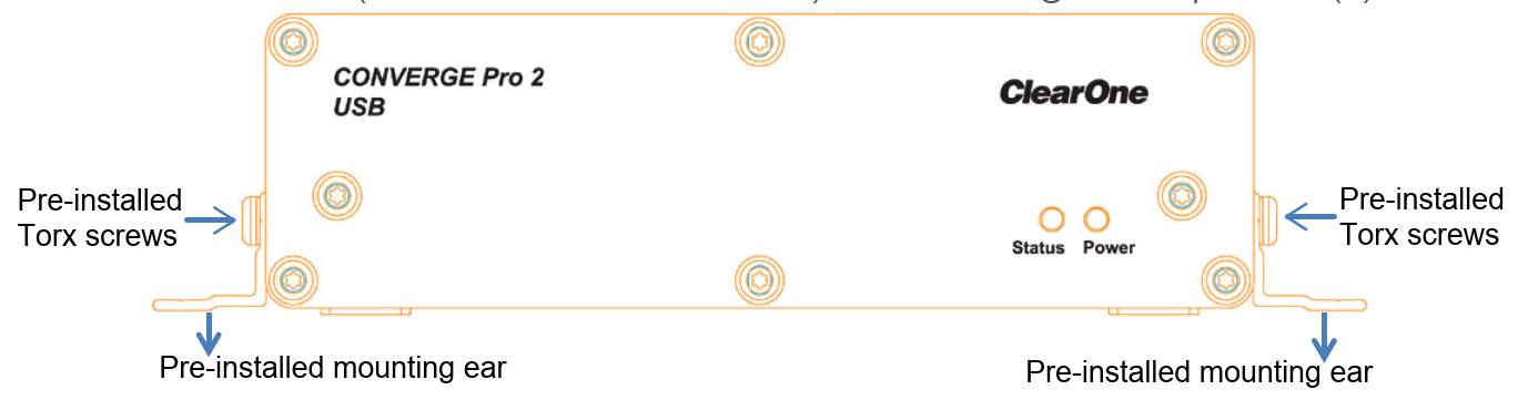
NOTE: Remove pre-installed mounting ears on expander to fit up to 3 expander units side-by-side on a single ClearOne 1U rack shelf.
4. Torx drive screws secure the pre-installed mounting ears to the main body of the expander unit. Remove them with a Torx T15 screwdriver (optional).
5. Secure expander unit(s) to the rack shelf. You must supply your own hardware (four #6 or M3.5 screws) for securing the expander(s).
Mounting Under The Table
Mounting hardware is not provided. Select your own hardware based on your specific installation needs.
1. Determine location for the mount.
2. Using expander as a guide (and level if needed), mark four mounting hole locations with a pencil.
3. Determine proper depth and diameter, and drill four pilot holes for the #6 or M3.5 screws.
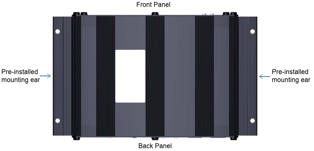
4. Align mounting holes on expander mounting ears with pilot holes.
5. Insert four #6 or M3.5 screws and tighten.
Mounting On The Wall
Mounting hardware is not provided. Select your own hardware based on your specific installation needs.
1. Determine location for the mount.
2. Using expander as a guide (and level if needed), mark four mounting hole locations with a pencil.
3. Drill four pilot holes for fasteners/anchors using proper size drill bits.
4. Install fasteners/anchors.
5. Align mounting holes on expander mounting ears with pilot holes.
6. Insert four #6 or M3.5 screws and tighten.
Note: Anchors and screws used to mount the expander are not provided and must be selected by installer for the type of wall material supporting the expander. Take care while drilling and installing anchors so wall material does not tear out and weaken attachment.
Mounting Above The Ceiling
Mounting hardware is not provided. Select your own hardware based on your specific installation needs.
Note: It is the installer’s responsibility to ensure that the installation and cable routing complies with local safety codes.
1. Determine location for the mount, and where to route cables. Mark location where you want to route cables through with a pencil (on finished side of ceiling tile) if you need to cut a hole.
2. Remove affected ceiling tile and adjacent tiles required for access.
3. Install fasteners/anchors.
4. Install expander unit at determined location.
5. Use drywall saw to cut hole into finished side of ceiling tile at marked location.
6. Route the cables through the hole.
NOTE: Carefully run connected cables so they do not block the cooling vents or put strain on the connectors.
NOTE: Anchors and screws used to mount the expander are not provided and must be selected by installer for the type of ceiling material supporting the expander. Take care while drilling and installing
anchors so ceiling material does not tear out and weaken attachment.
CONNECTIONS
Connect the USB expander to:
• Peripheral Link (P-Link) In or Power-over-Ethernet (PoE) power injector with a CAT5e or CAT6 cable,
• A laptop/PC/MAC, other audio devices, or VC codec with the Audio USB port via the Type A to Type B USB cable,
• A remote control serial device (such as ClearOne’s Touch Panel Controller, or any 3rd-party controller) with the RS232 port via the 3 Position Terminal Block Plug 3.81mm GY connector.
Back Panel
The CP2 USB Expander can be powered by a standard PoE injector, or a P-Link connection.
Set the Power Select switch towards P-Link In or PoE In based on the power source.
The P-Link In and Out ports enable you to connect with a CP2 unit or other P-Link devices. P-Link connections carry power, control and audio through CAT5e or CAT6 cable.
When not supplying power to an expander via a P-Link connection, power an expander via PoE by connecting a PoE Power Injector to the PoE In port.


Front Panel
- Power LED
- Off - not powered
- Solid Blue - powered
- Status LED
- Off - No P-Link plugged in
- Solid Blue - P-Link plugged in and system working normally
- Flashing Blue - Locate mode initiated from CP2 Console Software
- Red - Error condition

Detailed instructions on using the Locate function in the CP2 CONSOLE/CONSOLE AI
software can be found in the CONVERGE Pro 2 CONSOLE/CONSOLE AI User Manual
at: https://www.clearone.com/rl-home
CONFIGURE THE USB EXPANDER
CONVERGE Pro 2 CONSOLE/CONSOLE AI software is required for configuring CP2
and expander units.
The CP2 CONSOLE/CONSOLE AI uses auto-discovery when in online mode to help identify and list the expanders under the P-Link Devices section. Expander ports function and respond exactly as the ports directly on the CP2 unit.
Phases of the software setup include:
- Create a new or open an existing project
- Add a CP2 and peripheral devices to a project
- Configure stack/device settings
- Configure and manage Room (Space) settings
- Add USB to rooms where necessary
- Creating and managing Room Partition settings
- Configure USB Transmit and Receive channel settings
- Configure gating settings for microphones
- View project file status
- Send the configurations
The steps in these processes are detailed in the CONVERGE Pro 2 CONSOLE/CONSOLE AI User Manual at: https://www.clearone.com/rl-home
PART NUMBERS
910-3200-302 CONVERGE Pro 2 USB Expander
910-3200-301 CONVERGE Pro 2 GPIO Expander
910-3200-202 PoE+ Power Supply Kit for 3 devices
910-001-004 PoE Power Supply for 1 device
910-6106-001 1U Universal Rack-Shelf
910-3200-204-50 50 Ft RJ45 CAT6 Cable
910-3200-204-100 100 Ft RJ45 CAT6 Cable
910-3200-204-150 150 Ft RJ45 CAT6 Cable
910-3200-204-200 200 Ft RJ45 CAT6 Cable